atto-Systems OODGoto atto-Systems OOD
Intro
Applications
Features
Products
Solutions
Workflow
Details
Tools
Downloads
History
Gallery
Support
Contact
AreaCheck

Description :

The AreaCheck is a simple, but quite powerfull program, that could be used to solve different types of applications, like checks for presence, absence, completeness or even position. It is quite fast and easy to use. The optional working mode with relative thresholds provides stability against moderate changes in the ambient brightness, like changes in material, surface or lighting conditions.

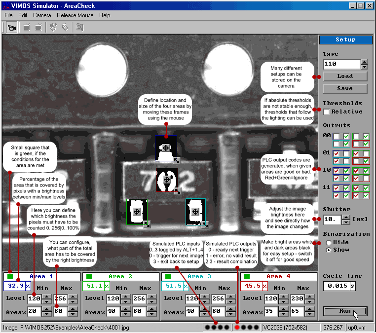
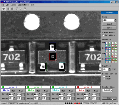
Below you can find a detailed example that uses the AreaCheck. It might help with the following description of the functionality and the user-interface.

Please have a look at the user-interface of the program. The notes next to the various elements should explain the usage. Sorry for the small letters. Note, that the image shows the camera program inside the window of the VIMOS PC Simulator. When you run it on the camera, the surrounding window will not be generated. The main reason for displaying images including the Simulator was to make the states of the PLC outputs visible. They are given by the four red ‘LEDs’ in the statusbar of the Simulator - down below the image. These ‘LEDs’ are black, when the corresponding PLC output of a real camera would have been ‘off’ and red, when it would have been ‘on’.

Performance :

The performance of the Simulator on the PC can not be used to estimate actual camera performance for many reasons. The given cycle time has been achieved on a VC2028. The shutter time of 10 ms is included, so reducing the shutter (i.e. by using bright light) would also reduce the cycle time. Please note, that this is not the fastest possible time that could be achived with VIMOS for this application. The following ways exist to get better performance :

The VC2028 captures images comparatively slow (25/s = 40ms) so a camera with faster image capture could be used (VC2038 = 40/s = 25ms, VC2048>100/s=10ms).

VIMOS supports image capture in the background, so that the next image can be captured while the actual one is being processed. That would eliminate the shutter time and the capture time as long as they are shorter then the processing. It also makes it more difficult for the user to understand, when the camera is ready for the next trigger and to make the correct connection between the results and the objects they came from. We would assist to use this high-performance mode.

To get the highest performance, one would of course have to ‘live’ without any drawings. At the moment even during the run-mode the frames around the areas and the major results are displayed. There are also some small settings in the configuration that could be changed for higher performance.

The actual ‘slow’ configuration was chosen to make it easy to begin to work with this VIMOS program. Under the described conditions one cycle has been executed in about 90 ms. On a VC2038 with 5 ms shutter that would give about 70 ms. If you need higher speed, please contact us, there are options.

Example :

Determining the orientation of chips in SOT23 packages sitting in the shipping reel :

Semiconductors are shipped in many different packages. The AreaCheck solution can be used to check, that all chips have the right orientation in their compartments.

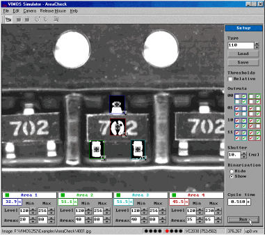
As an example the SOT23 package was chosen to demonstrate the work of the AreaCheck. The four working areas are positioned in such a way, that the correct brightness of the three pins and the printing on the plastic casing can be checked.

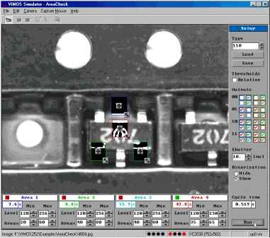
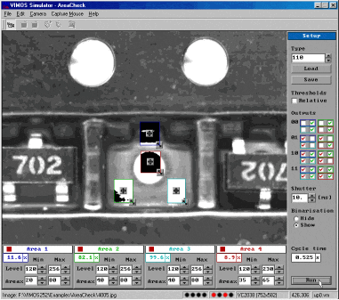
Only when all four areas find the required brightness levels and extensions, the camera produces result ‘00’ on its two PLC outputs reserved for that purpose. The rotated chip is announced by ‘01’ and flipped or missing chips produce result ‘10’. Combination ‘11’ is not used in this example.

Reel

Good orientation
- all 4 areas
green
- result on the PLC outputs : 00

Wrong orientation
- 3 areas around the pins
fail
- result on the PLC outputs : 01

Missing chip
- all 4 areas
fail
- result on the PLC outputs : 10

Flipped chip
- central area
fails
- result on the PLC outputs : 10

The information may be outdated or accidentally wrong and is given without guarantee. (C) 2002 J. Beutel

Please read the legal information you find at our imprint.